
Electrical Principles.
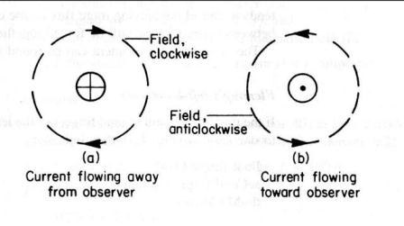
Electromagnetism. Field around a conductor carrying a current, When a conductor carries a current, a magnetic field is produced around that conductor. This field is in the form of concentric circles along the whole length of the conductor. The direction of the field depends on the direction of the current, clockwise for a current flowing away from the observer and anti-clockwise for a current flowing towards the observer.
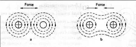
Force between current carrying conductors. If we place two current carrying conductors side by side there will exist a force between them due to the flux. The direction of this force will depend on the directions of the current flow.
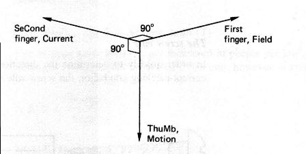
In Fig a above there is more flux between the conductors than on either side of them, and they will be forced apart. In Fig b above the flux between the conductors is in opposite directions and tends to cancel out leaving more flux on the outside of the conductors than in between them, so they will bw forced together. Fleming’s Left Hand Rule. If the thumb, first and second fingers of the left hand are placed at right angles to one another, they indicate, as shown in the figure below; first finger = field second finger = current thumb = motion
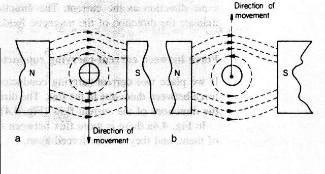
Force on a conductor carrying a current in a magnetic field. If we arrange for a current carrying conductor to be placed at right angles to a magnetic field, a force will be exerted on that conductor, see figure below, this force is measured in newton’s.
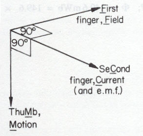
In the figure (a) above, the flux above the conductor is greater than the flux below, and the conductor is forced downwards. In figure b, the current and hence the field around the conductor is opposite to that in figure a and the conductor is forced upwards. The magnitude of this force is dependent on three things. 1/. The current flowing in the current (I). 2/. The density of the magnetic field (B). 3/. The length of the conductor in the magnetic field (l) F (newtons) = B (teslas) x l (metres) x I (amperes) Example Calculate the force exerted on a conductor 40 cm long carrying a current of 100A at right angles to a magnetic field of flux density 0.25T. B = 0.25T l = 0.4m I = 100A So F = B x l x I = 0.25 x 0.4 x 100 = 10N Example A circular magnetic field has a diameter of 20cm and a flux of 149.6 mWb. Calculate the force exerted in a conductor 21cm long lying at right angles to this field if the current flowing is 15A. B = F/a but a = pd2/4 so a = 3.1416*0.2*0.2/4 = 0.031416 m2 B = F/a = 149.6*10-3/0.031416 = 4.762 T F = B*l*I 4.762*0.21*15 = 15 N E.M.F induced in a moving conductor. We have seen that passing a current through a conductor in a magnetic field produced a movement of that conductor. If we reverse the process and physically move the conductor through a magnetic field, such that it cut across the flux, then a current would flow in that conductor. This means that an e.m.f. must be present across the conductor and is called an induced e.m.f. The direction can be determined using Fleming’s right hand rule.
If the thumb, first and second finger are arranged At right angles to one another (on right) they indicate First finger, Field (north to south) seCond finger, Current (and e.m.f.) thuMb, Motion
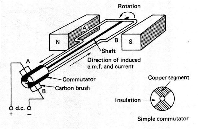
The magnitude of the induced e.m.f. depends upon: 1/. the flux density of the field (B) 2/. the length of the conductor (l) 3/. the velocity at which the conductor cuts across the flux (v) so E(volts) = B(teslas) * l(metres) * v(metres/second) Example A conductor 15cm long is moved at 20 m/s perpendicuarly through a magnetic field of flux density 2T. calculate the induced e.m.f. E = B * l * v = 2 * 0.15 * 20 = 6V DC Generator. Below is shown a simple d.c. generator, as the coil of wire is rotated by a prime mover in the direction shown side A travels down and side B up, The current and hence the induced e.m.f. will be in the direction shown making brush A +ve and brush B –ve. After 1800 revolution side A will be traveling up and side B down, but the induced e.m.f. stays in the same direction and so the polarity at the brushes remains unchanged. We have therefore generated a d.c. source of supply.
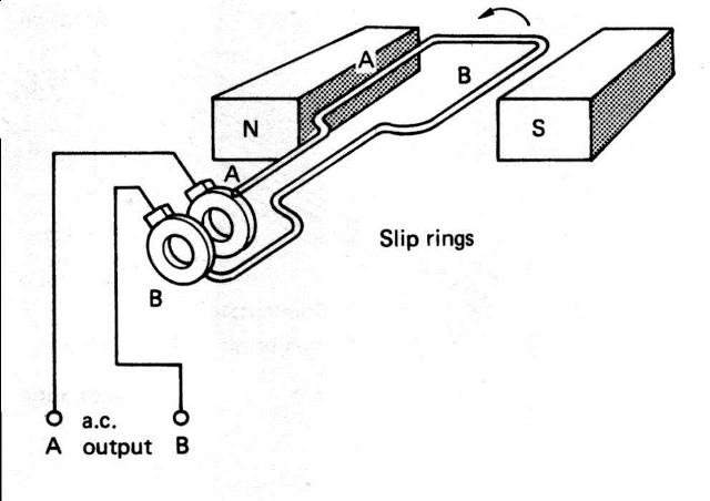
In a larger more practical generator the magnetic field would be provided by electromagnets rather than permanent magnets. The single loop would be replaced by many loops, called an armature, the comutator would have many insulated segments to which the ends of the loops are connected, and the iron core would be laminated to reduce eddy currents. A.C. Generator. The principle of a.c generation is much the same as for d.c. however in the a.c. case the ends of the coils are terminated in slip rings, not a commutator. Because of this arrangement, slip ring A (see dia below)always being connected to side A the induced voltage would start off in the position shown with maximum voltage induced in it in one direction, as it rotates through 1800 the voltage will fall to zero and then rise to a maximum in the opposite direction. As it rotates through another 1800 the voltage again falls to zero and rises to a maximum in the original direction. In other words it alternates from positive maximum through zero to negative maximum through zero again back to positive maximum.
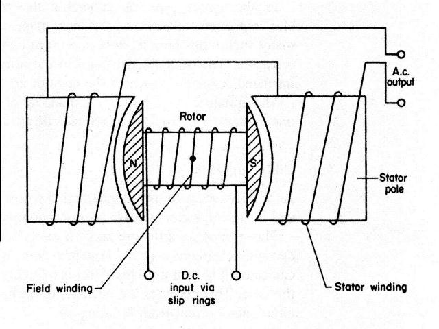
In practice the arrangement shown below is prefered where the magnetic field rotates and the output is taken from the fixed coils.
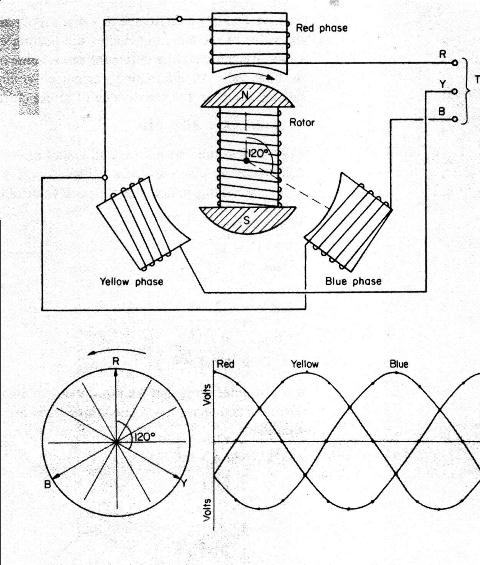
Note : RMS value = root mean squared = Irms = Imax * 0.7071 Average value = Iave = Imax * 0.637 Three Phase Generation. The principle of generating a three phase supply is the same as for single phase except that the field coils are set 1200 apart, one end of each coil is connected to a centre (or star) point the other ends going out as red phase, yellow phase and blue phase. (Since 1st April 2004 the new colours for 3 phase supplies are brown, black and grey) In the position shown below the induced e.m.f. in the red phase is at a maximum, in the yellow phase it is increasing and in the blue phase it is decreasing. The resulting waveforms are shown below. If the voltages in the 3 phases are added together at any moment in time the resultant voltage is zero. Hence in a balanced three phase system the resultant voltage and current is zero.
Induced e.m.f. due to change in flux. A changing magnetic field induces a current into a conductor, the e.m.f. driving this current is called the back e.m.f. and is given by the formula
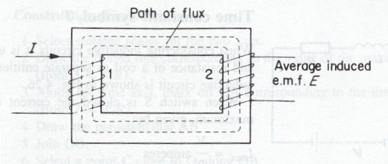
E = -(F2-F1/t)*N in volts Example The magnetic flux linking the 1800 turns of an electromagnet changes from 0.6 mWb yo 0.5 mWb in 50 ms. Calculate the average value of the induced e.m.f. E = -(F2-F1/t)*N = -((0.6-0.5)/50*10-3)*10-3*1800 = -(0.1*1800)/50 = -3.6 V Self Inductance. Self-inductance is the property of a coil in which a change of current, and hence a change of flux, produces an e.m.f. in that coil. The average induced e.m.f. in such a circuit is given by; E = (-L(I2-I1)/t volts The inductance L is given by L = (N*F)/I The unit of inductance is the henry (H) and is defined as follows; A circuit has an inductance of 1 henry when an e.m.f. of 1 volt is induced in that circuit by a current changing at a rate of 1 ampere per second. Mutual inductance. Symbol (M), unit henry (H) If we wind two coils of wire on the same iron core, then a change of current in coil 1 produces a change of flux which will link with coil 2 thus inducing an e.m.f. in that coil. These two coils are said to possess the property of mutual inductance.
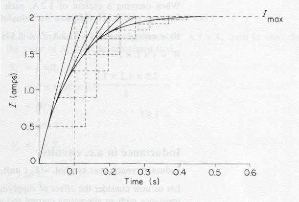
A mutual inductance of 1 henry exists between two coils when a uniformly varying current of 1 ampere/second in one coil produces an e.m.f. of 1 volt in the other coil. If a change of current (I2 – I1), in the first coil, induces an average e.m.f. E in the second coil, then: M = (F2-F1)/(I2-I1)*N in henry's Time constant. Symbol (T) In an inductive circuit it is best to represent the inductance and resistance as separate entities, L and R. When a typical inductive circuit is energised the current rises to a steady maximum of I = V/R the time taken for this to happen is called the time constant and is given by the formula T = L/R seconds. Example A coil having a resistance of 25W and an inductance of 2.5 H is connected across a 50 volt d.c. supply. Derive the curve of the current growth. Imax = V/R = 50/25 = 2A; time constant T = L/R = 2.5/25 = 0.1 seconds
Energy stored in a coil (W) W = 1/2 * L* I2 joules Example When carrying a current of 1.2 A each field coil of a generator has an inductance of 2.5 H. Calculate the value of the energy stored in each coil. W = 1/2 * L * I2 = 0.5 * 2.5 * 1.2 = 1.8 JInductance in a.c. circuits.
Inductive reactance. Symbol XL, unit W If we supply an iron cored coil with a.c. the current and hence the magnetic field is building up and collapsing 50 times a second and hence a continual alternating back e.m.f. is produced which is opposing the change that produced it, therefore there is a continuous opposition to current flow, this opposition is called the inductive reactance XL measured in ohms. XL = 2 * p * f * L ohms Example Calculate the inductive reactance of a coil of inductance 0.5 H when connected to a 50 Hz supply. XL = 2 * p * f * L = 2 * 3.142 * 50 * 0.5 = 157.1 ohms When an a.c. supply is given to a pure inductance the principles of ohms law may be applied i.e. V = I * XL. Home page. Electrics Home page. Previous page. Next page.